
Continuous Release of IGBT Vitality, In-depth Discussion on Key Induction Heating Technologies
Featuring advantages such as fast heating speed, no open flames, high output power, high conversion efficient from electrical energy to thermal energy, and low system costs, induction heating has become widely used in the home appliance market. Concurrently, manufacturers and end users are demanding more precise performance for these systems. Therefore, it is essential to design a high-power, highly reliable, and highly integrated induction heating system.
In this issue, we will explore the exceptional capabilities of WeEn's RC-IGBTs, focusing on the WG30R135W1 and WG30R140W1.
Taking induction cooker as an example, alternating current passes through the coil then, generate the alternating magnetic field. The conductor placed within this magnetic field experiences eddy currents, and the Joule heating effect of these currents causes the conductor to heat up, thereby achieving the heating purpose.
The diagram below illustrates the typical structure and circuit block diagram of an induction cooker. The primary energy source is the alternating current generated by the single-end inverter, which compose of cookware, capacitor, and an IGBT. The IGBT serves as the core component of this single-end inverter. The RC-IGBT is particularly well-suited for induction heating applications because it combines the superior performance of an IGBT with the reliable freewheeling capability of an anti-parallel diode.
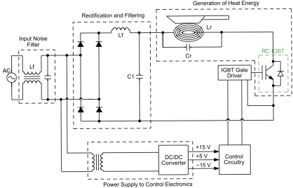
Figure 1: Typical Structure and Circuit Block Diagram of an Induction Cooker
Taking WeEn latest RC-IGBT parts WG30R135W1 and WG30R140W1 as examples, WG30R135W1 is rated for 1350V, while WG30R140W1 is rated for 1400V. Both parts have the same current rating of 30A and house in TO247 package. These products offer customers greater design flexibility and allow the handling of complex and challenging induction cookers application scenarios, thereby aiding manufacturers in their design and application processes.
The diagram below shows the temperature rise test results conducted on several domestic and international products with similar specifications. The test was performed at an ambient temperature of 25ºC with 10 minutes of operation, after which the case temperature of the devices was recorded. The comparison results indicate that WeEn's RC-IGBT products exhibit the best thermal performance among similar products, primarily due to the lower losses of the RC-IGBT.

Figure 2: Temperature Rise Test Performance
Due to the varying cooking habits and application scenarios, the operating conditions of induction cookers are often highly complex. For instance, during pan detection or startup, the IGBT may not achieve Zero Voltage Switching (ZVS). During these moments, current flows directly through the capacitor, resulting in very high pulse currents. This requires the IGBT to switch on successfully under high voltage and large pulse current conditions, ensuring that the waveform remains smooth and free from oscillations.
The diagram below shows the switching waveforms of WeEn RC-IGBT products compared to one domestic competitor under these conditions. It is evident that WeEn RC-IGBT products achieve stable and smooth switching waveforms under high voltage and large pulse current conditions, offering greater reliability.
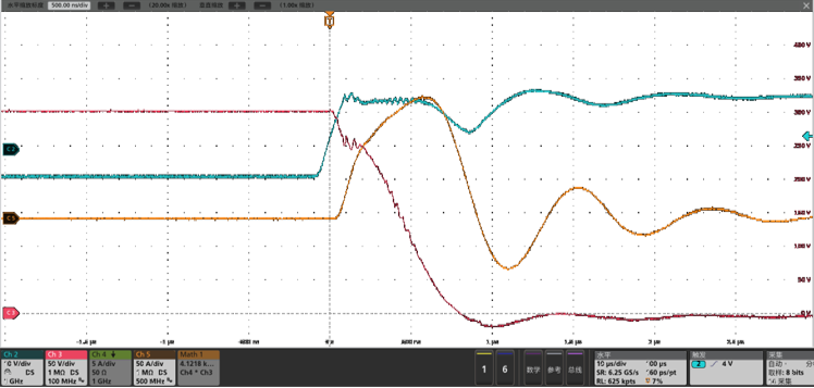
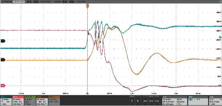
Figure 3: Comparison of the Switching Waveforms of WeEn RC-IGBT Products (top) and one Domestic Competitor (bottom)
Due to the diverse application scenarios, such as moving or shaking the pot or encountering surges, these require the IGBT must have a high breakdown voltage rating to avoid the failure. The diagram below shows test results conducted in the laboratory based on customer conditions, demonstrating that WeEn RC-IGBT products have strong breakdown voltage resistance and higher reliability.
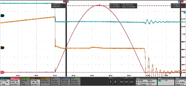
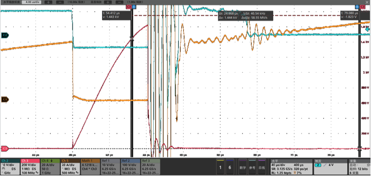
Figure 4: Comparison of the Waveforms of WeEn RC-IGBT Products (left) and one Domestic Competitor (right) under Unpredictable Induction Cooker Conditions
Understanding RC-IGBT
RC-IGBT stands for Reverse Conducting Insulated Gate Bipolar Transistor. It is an important branch of the IGBT product family, developed to meet different application characteristics.
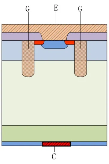
Figure 5: Cross-Sectional Diagram of WeEn RC-IGBT
The RC-IGBT mainly replaces a portion of the P-region in the collector with an N-region, forming a PIN diode with the P-region in the emitter. Typically, IGBT products require an anti-parallel diode. However, the RC-IGBT smartly integrates the freewheeling diode chip into the IGBT chip, effectively enhancing wafer utilization. This integration improves device performance and reduces costs. RC-IGBTs have become the preferred choice for induction heating applications.
For more information, please visit https://www.ween-semi.com